ESP32 Point Cloud Scanner
2026-03
A real-time 3D point cloud scanner built on an ESP32. A VL53L5CX time-of-flight sensor captures an 8x8 depth grid at 15 Hz, a BNO08x IMU tracks orientation via quaternion, and the fused data streams over WiFi to a browser-based Three.js viewer, all served directly from the microcontroller.
Github Repository: Here
# What it does
Point the scanner around a room and watch a 3D point cloud build up in your browser in real time. The VL53L5CX sensor covers a 64-zone (8x8) field of view, measuring distances at 15 frames per second. Each depth reading gets projected into world space using pre-calibrated pitch and yaw angles per zone, then rotated by the live IMU quaternion so the points land in the right place. The whole web interface can be served from the ESP32's flash using LittleFS.
Real-time point cloud of a room, built up by sweeping the scanner around
# The pipeline
The firmware runs a tight polling loop: check if ToF data is ready, read the IMU quaternion at the same moment, pack both into a 208-byte binary frame, and broadcast it over WebSocket. Binary instead of JSON because the ESP32 is doing this 15 times per second and doesn't need the overhead of serializing strings, a JSON equivalent would be around 800 bytes per frame.
On the browser side, frames go into a Web Worker where Kalman filtering runs off the main thread so the render loop stays smooth. The filtered distances then get transformed into 3D points and written into a circular buffer, once full, old points start getting overwritten, keeping memory use fixed at 262,144 points.
On the browser side, frames go into a Web Worker where Kalman filtering runs off the main thread so the render loop stays smooth. The filtered distances then get transformed into 3D points and written into a circular buffer, once full, old points start getting overwritten, keeping memory use fixed at 262,144 points.
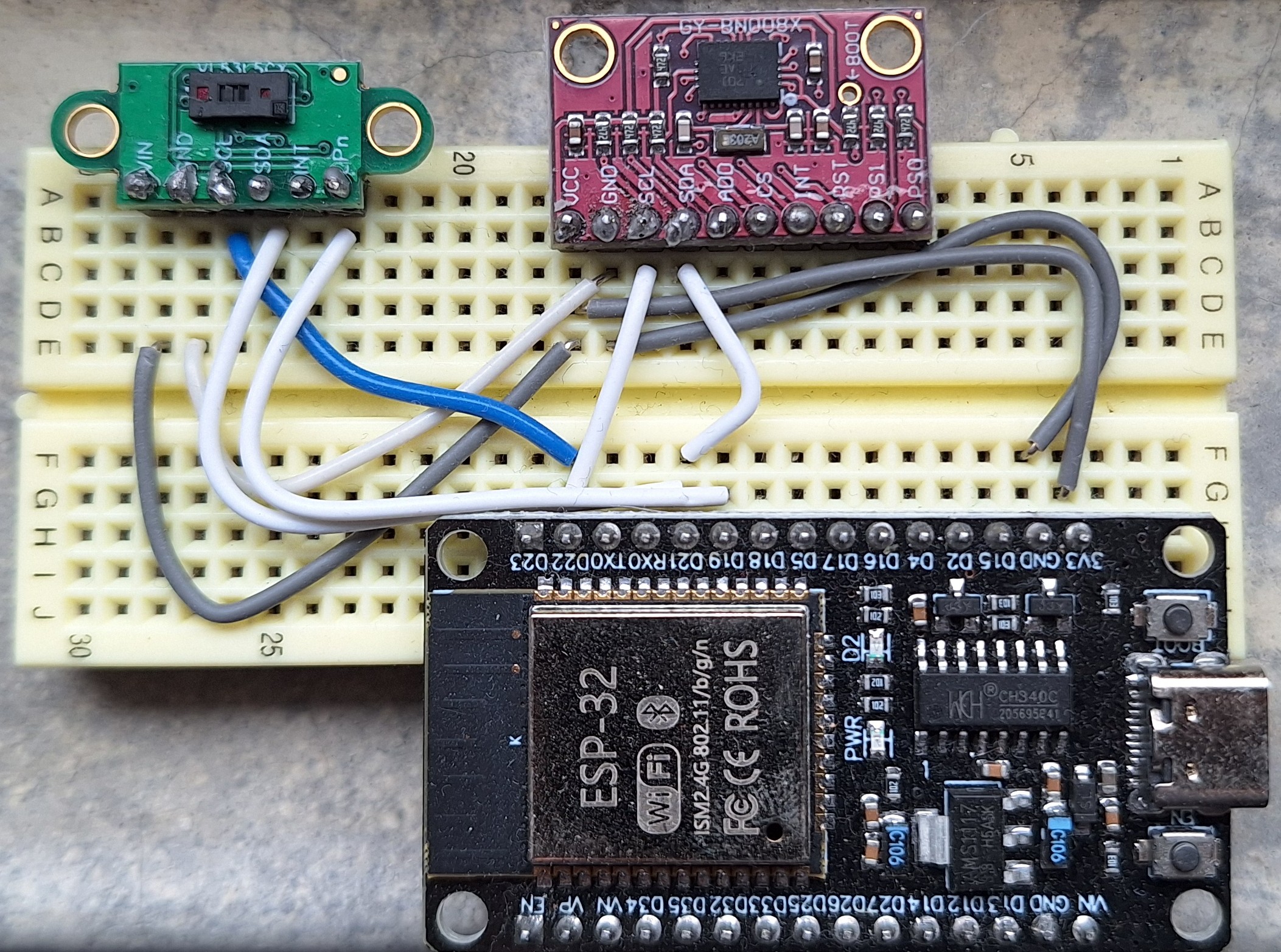
The full hardware setup: ESP32, ToF sensor, and IMU, all on a shared I2C bus
# Kalman filtering and edge cases
The raw sensor readings are pretty noisy, the same zone bouncing between slightly different values each frame even when nothing is moving. A Kalman filter fixes that by keeping a running estimate of the true distance and blending each new measurement into it, rather than just using whatever the sensor says this frame. The less you trust the sensor (higher R), the more it smooths. The more you expect the real value to change (higher Q), the faster it follows. Getting those two numbers to feel right took some trial and error.
The trickier part was figuring out when NOT to filter. If the sensor is rotating, blending the old estimate with new measurements from a completely different part of the room produces garbage, so when the IMU detects movement the filter resets entirely. Same thing at depth edges: if a zone suddenly jumps 250mm it has probably crossed from one surface to another, and smoothing across that would blur the edge away. So that resets too.
Kalman filtering was completely new to me going into this. The predict-update loop took a while to actually make sense. But at one point it clicked, and I could see the point cloud go from jittery noise to something a little more stable and clean.
The trickier part was figuring out when NOT to filter. If the sensor is rotating, blending the old estimate with new measurements from a completely different part of the room produces garbage, so when the IMU detects movement the filter resets entirely. Same thing at depth edges: if a zone suddenly jumps 250mm it has probably crossed from one surface to another, and smoothing across that would blur the edge away. So that resets too.
Kalman filtering was completely new to me going into this. The predict-update loop took a while to actually make sense. But at one point it clicked, and I could see the point cloud go from jittery noise to something a little more stable and clean.
# What's next
The obvious next step is SLAM, Simultaneous Localization and Mapping. Right now the scanner only works well when you hold it fairly still (positionally speaking, rotation is fine), because the IMU tracks orientation but not position. SLAM would let it track where it is in space while scanning, meaning you could walk around a room and build up a full map as you go. That is a much harder problem but also a much more interesting one, and I have been watching videos about it. The math is genuinely cool.
If SLAM ever works, a silly but very fun follow-up would be to pipe the scan directly into Minecraft and reconstruct whatever room you scanned as blocks. Scan your house, get your house in Minecraft. No idea how hard that actually is, but it is a very motivating idea to keep going.
If SLAM ever works, a silly but very fun follow-up would be to pipe the scan directly into Minecraft and reconstruct whatever room you scanned as blocks. Scan your house, get your house in Minecraft. No idea how hard that actually is, but it is a very motivating idea to keep going.
# Calibration and export
The VL53L5CX zones are not perfectly uniform in sensitivity, when pointing straight up they kind of show a parabola? So I built a calibration routine into the viewer. Hold the sensor still, click calibrate, and it collects 180 frames while enforcing an IMU motion check, then computes per-zone scale and offset corrections. The geometric calibration (the pitch and yaw angles that map each of the 64 zones to a direction in 3D space) was calculated from the sensor's datasheet optics and baked into a lookup table.
Once calibrated, the accumulated point cloud can be exported as a PLY file with a Blender coordinate transform already applied (Y-up to Z-up, 180° Y rotation) so it drops straight into Blender without needing to fix the orientation manually.
Once calibrated, the accumulated point cloud can be exported as a PLY file with a Blender coordinate transform already applied (Y-up to Z-up, 180° Y rotation) so it drops straight into Blender without needing to fix the orientation manually.